Hydraulic Oil Cooling System for Heavy Equipment: Key Design Factors
A hydraulic oil cooler can look correctly sized on a datasheet and still fail to control oil temperature once the machine starts working. In heavy equipment, this is rarely explained by cooler size alone. The real result depends on the heat generated by the hydraulic circuit, how long that heat load lasts, how much oil actually passes through the cooler, the pressure loss in the return circuit, the temperature and volume of cooling air, and where the cooler is installed.
For excavators, loaders, mining equipment, agricultural machinery, and other mobile machines, hydraulic oil cooling system design therefore has to begin with the actual operating condition rather than a catalogue model number.
A cooler should be selected for the heat the machine must reject under real duty—not simply for pump power, nominal oil flow, or available installation space.
The following factors are the ones that most often separate a cooling system that performs well on a test sheet from one that continues to control temperature in the field.
Start With the Real Hydraulic Heat Load
The first design question is not “What size cooler fits the machine?” It is “How much heat must the cooling system remove?”
Hydraulic systems do not convert all input power into useful mechanical work. Energy is lost through pump and motor inefficiency, pressure reduction across valves, internal leakage, line restriction, throttling, and mechanical friction. Much of that lost energy eventually appears as heat in the hydraulic oil.
This distinction matters because two machines using pumps with similar rated power can have very different cooling requirements. One may operate efficiently at moderate pressure for most of its cycle, while another spends long periods throttling flow, working close to relief pressure, or driving high-load attachments.
Two Useful Ways to Estimate Heat Load
During early design, hydraulic losses can be estimated from input power, useful output, pressure losses, pump efficiency, valve losses, and expected operating cycle. This is useful when the machine has not yet been instrumented.
If actual oil flow and temperature change across the cooler can be measured, heat rejection can also be estimated from the oil mass flow and temperature difference.
Heat transfer relationship:
Q = ṁ × Cp × ΔT
Q = heat transfer rate
ṁ = oil mass flow rate
Cp = specific heat capacity of the oil
ΔT = oil temperature change
The formula is useful, but it should not become the entire sizing method. A hydraulic oil cooling system must still be checked against changing duty, airflow, viscosity, pressure drop, contamination, and installation conditions.
Design for Duty Cycle, Not Just Maximum Pump Power
Heavy equipment rarely operates at one steady load. An excavator may alternate between travel, swing, digging, lifting, attachment operation, and idle. A loader may spend part of its cycle filling the bucket, part traveling, and part unloading. Each operating stage creates a different hydraulic loss and therefore a different heat load.
This is why maximum pump power alone is a poor description of thermal duty.
| Operating Condition | Thermal Importance | Design Question |
|---|---|---|
| Short peak load | May raise temperature temporarily | How long does the peak continue? |
| Continuous moderate load | Can create a larger accumulated heat load | Can the cooler reject heat continuously? |
| Frequent relief operation | Converts pressure energy directly into heat | Is relief flow part of normal operation? |
| High-flow attachment | Changes both hydraulic load and oil flow | Was the original cooling system designed for it? |
| Idle or low-load period | Allows heat generation to fall | How much recovery time exists between peaks? |
A system that experiences a high load for thirty seconds every ten minutes does not behave thermally like one that remains near high load for thirty minutes. Good hydraulic oil cooling system design therefore separates continuous duty from intermittent peak duty.
This also explains why some machines operate normally during short tests but run hot after one or two hours in production. The test confirms that the machine works; it does not necessarily confirm that the cooling system has reached thermal equilibrium under the real duty cycle.
Oil Flow Through the Cooler Must Be Known, Not Assumed
Another common mistake is to use maximum pump flow as though the same volume must pass through the cooler at all times. The actual cooler flow can be different depending on circuit layout, return paths, bypass valves, auxiliary circuits, and operating mode.
For this reason, cooler selection should be based on the flow that actually enters the cooling circuit.
Why Flow Rate Matters
Oil flow affects both heat transfer and pressure loss. If the flow is much lower than expected, the cooler may not receive enough hot oil to remove the required heat from the system. If the flow is much higher, oil-side velocity and pressure drop may rise beyond the intended range.
The relationship is not simply “more flow equals more cooling.” A useful design balances heat transfer, acceptable pressure loss, connection size, internal flow passage geometry, and the hydraulic circuit's operating limits.
Variable Flow Makes the Problem Harder
Mobile equipment often sees large changes in return flow. A cooler may therefore need to operate over a range of oil flows rather than at one fixed design point.
That is especially important where attachments are changed or where multiple hydraulic functions can operate simultaneously.
Pressure Drop Is Part of the Thermal Design

A hydraulic oil cooler is not thermally successful if it removes heat efficiently but creates excessive restriction in the oil circuit.
Pressure loss can occur through the cooler core, hoses, fittings, elbows, valves, filters, and long return lines. As restriction increases, the hydraulic system must spend more energy moving oil through the circuit. That energy loss can become additional heat—the exact problem the cooler is intended to control.
Heat rejection and pressure drop must be evaluated together. Improving one while ignoring the other can produce a poor hydraulic cooling system.
This becomes particularly important at high flow rates and during cold start, when hydraulic oil viscosity may be significantly higher than at normal operating temperature.
Do Not Check the Core Alone
The cooler may have an acceptable pressure drop by itself while the complete installation does not. Port size, hose diameter, fittings, return-line routing, filters, and bypass valves all contribute to the total resistance seen by the hydraulic circuit.
For OEM or custom cooler development, pressure-drop evaluation should therefore use the expected fluid viscosity and flow range rather than a single ideal operating point.
Oil Viscosity Changes the Design Condition
Hydraulic oil does not have constant flow behaviour. Viscosity changes with temperature, which means the same cooling circuit can behave very differently at startup and after the machine reaches normal operating temperature.
Cold Oil
Higher viscosity increases resistance through the cooler and connecting lines. Pressure drop may therefore be highest when the machine is cold, even though the system does not yet require maximum heat rejection.
Warm Operating Oil
As viscosity falls, oil passes through the cooler more easily. At the same time, the hydraulic system may be producing much more heat, so thermal capacity becomes the dominant requirement.
This creates an important engineering trade-off: the cooler must handle the thermal load at operating temperature without creating unacceptable restriction when the oil is colder.
Depending on the circuit, a bypass arrangement may be used to protect the cooler or prevent excessive pressure during high-viscosity conditions. The required approach depends on the hydraulic system and should not be selected from a generic pressure value alone.
Use the Real Cooler Inlet Air Temperature
Ambient temperature is a standard input in cooler selection, but for heavy equipment the outside air temperature may not be the temperature actually entering the cooler.
A cooler installed inside a compact engine compartment can receive air that has already been heated by the engine, radiator, charge air cooler, hydraulic components, or exhaust system. Hot air can also recirculate from the discharge side of the cooling package back toward the intake.
As a result, a machine working in 35°C ambient conditions may expose the oil cooler to significantly warmer inlet air depending on the installation.

Why the Difference Matters
Air-cooled heat exchangers depend on the temperature difference between the hot oil and the cooling air. When cooler inlet air becomes hotter, that temperature difference becomes smaller and the available heat-rejection capacity falls.
For this reason, design calculations should use a realistic worst-case inlet-air condition where possible—not simply a regional weather temperature copied into a specification sheet.
If you need a comparison of air-cooled and water-cooled hydraulic oil cooling methods, see our existing guide to how to cool hydraulic oil. The focus here is different: once the cooling method is selected, the installed conditions still determine whether the system can deliver the required performance.
Fan Airflow Must Be Evaluated Through the Installed Cooler
Fan size or free-air airflow alone does not tell you how much air will actually pass through a cooler core.
As cooling air moves through fins, guards, screens, adjacent heat exchangers, ducts, and confined engine compartments, resistance increases. The fan must be able to deliver useful airflow against that resistance.
This is why two installations using the same fan and the same cooler may produce different oil temperatures.
The important airflow value is the air that actually passes through the heat-transfer surface—not the fan's theoretical airflow without system resistance.
Factors That Reduce Installed Airflow
Typical causes include insufficient intake area, restrictive guards, small discharge openings, dust accumulation, poor shroud sealing, low fan speed, recirculation of discharge air, and resistance from other heat exchangers in the same cooling package.
A larger fan is therefore not automatically the correct solution. Fan power, noise, available electrical or hydraulic drive power, pressure capability, packaging, and core resistance should be considered together.
Cooler Placement Can Change Real Cooling Capacity
Location is not simply a packaging decision. It is part of thermal design.
A cooler installed where it receives cool, unrestricted air may perform very differently from the same unit positioned behind another heat exchanger or deep inside an engine compartment.
Three Installation Questions Worth Asking
| Question | Why It Matters |
|---|---|
| What temperature air reaches the cooler? | Preheated air reduces the available temperature difference. |
| Can air leave the cooler freely? | Poor discharge space raises system resistance and encourages recirculation. |
| Can the core be accessed for cleaning? | A design that cannot be serviced may lose airflow long before the machine reaches the end of its life. |
Heavy equipment adds another constraint: vibration and shock. Cooler mounts, hoses, brackets, and connections should not transfer unnecessary mechanical loads into the aluminum core during machine operation.
Consider the Complete Cooling Package
Many heavy machines do not use the hydraulic oil cooler as a standalone heat exchanger. The cooling package may combine an engine radiator, hydraulic oil cooler, charge air cooler, transmission cooler, or other thermal components around one fan and one available airflow path.
That changes the design problem considerably.
If the hydraulic oil cooler receives air after it has already passed through another heat exchanger, its inlet air is warmer. If several cores are stacked in the airflow direction, their combined resistance also affects fan performance. If they are arranged side by side, sealing and air distribution become important because the fan may not pull the same volume through every section.
Thermal Interaction
Upstream heat exchangers can raise the air temperature seen by downstream components.
Airflow Interaction
Multiple cores, guards, and ducts increase total air-side resistance.
Control Interaction
One fan may have to satisfy several cooling demands that peak at different times.
For more background on how radiators, oil coolers, and charge air coolers operate together in construction machinery, see our guide to heavy equipment cooling systems.
For a new hydraulic cooling project, however, the important step is to evaluate the package as one thermal and airflow system rather than sizing each heat exchanger independently.
Allow Margin for Real Service Conditions
A new cooler tested with a clean core, full fan speed, controlled inlet air, and stable oil flow represents a best-case condition. Heavy equipment rarely stays in that condition.
Dust can accumulate between fins. Fan performance can decline. Guards may become partially blocked. Oil properties change with temperature and service life. Engine compartment temperatures vary with workload and weather.
The design therefore needs a realistic operating margin.
The correct margin is application-specific. A machine working in a clean indoor environment does not need the same allowance as an excavator operating around dust, fibers, mud, or high ambient temperature.
If a cooling system only meets the required oil temperature with a perfectly clean core, maximum fan airflow, and mild ambient conditions, it has very little field margin.
Key Data Needed Before Selecting a Hydraulic Oil Cooler
The quality of the design depends heavily on the quality of the input data. Sending only machine model and cooler dimensions may be enough to reproduce a physical part, but it is usually not enough to verify thermal performance for a new or modified application.
| Design Input | Why It Matters |
|---|---|
| Required heat rejection | Defines the thermal duty the cooler must remove. |
| Oil flow rate | Affects heat transfer, velocity, and pressure drop. |
| Oil type and viscosity | Changes fluid-side resistance and thermal behaviour. |
| Oil inlet temperature | Defines the hot-side operating condition. |
| Target oil temperature | Establishes the required thermal result. |
| Ambient or cooler inlet-air temperature | Determines the available temperature difference. |
| Actual airflow or fan data | Defines the air-side cooling condition. |
| Allowable pressure drop | Prevents the cooler circuit from adding excessive hydraulic resistance. |
| Duty cycle | Separates short peaks from continuous heat load. |
| Installation space and orientation | Controls core geometry, airflow path, and connection layout. |
| Dust and contamination level | Helps define realistic long-term cooling margin. |
| Machine and application | Provides context for vibration, workload, environment, and packaging. |
Common Hydraulic Cooling System Design Mistakes
Many field problems can be traced back to assumptions made before the cooler was selected. The following mistakes are more important than simply choosing a core that looks too small.
Sizing From Pump Power Alone
Pump power is useful information, but it does not directly tell you how much energy becomes heat. Efficiency, pressure losses, throttling, relief operation, and duty cycle determine the actual thermal load.
Using Peak Flow Without Checking Cooler Flow
Maximum pump flow and cooler flow are not always the same. Circuit routing and bypass behaviour should be understood before selecting port size and internal flow capacity.
Ignoring Pressure Drop
A high-capacity cooler can still be a poor choice if the oil-side restriction creates excessive backpressure or forces the system to waste additional power.
Using Outside Ambient Temperature as Cooler Inlet Temperature
Engine compartments and stacked cooling packages can expose the cooler to air that is considerably warmer than the surrounding environment.
Assuming Fan Rating Equals Core Airflow
Fan performance changes when air must pass through fins, guards, ducts, screens, and multiple heat exchangers. Installed airflow is what matters.
Designing for a Clean-New Condition Only
Dust, fouling, fan wear, and seasonal temperature changes gradually reduce available cooling margin. The initial design should account for the real service environment.
Sizing Each Heat Exchanger Separately
In a multi-cooler package, one core can change the air temperature and airflow available to another. Treating each heat exchanger as an isolated component can lead to optimistic performance estimates.
FAQ
How do you determine the required capacity of a hydraulic oil cooler?
Start with the heat that the hydraulic system must reject rather than simply matching cooler capacity to pump power. Heat load can be estimated from hydraulic losses or calculated from measured oil flow and temperature change. The result should then be checked against actual airflow, ambient conditions, pressure drop, duty cycle, and installation margin.
Does oil flow rate affect hydraulic oil cooler sizing?
Yes. Oil flow influences both heat transfer and pressure drop through the cooler. The important value is the actual flow through the cooling circuit, which may differ from maximum hydraulic pump flow.
How much pressure drop is acceptable across a hydraulic oil cooler?
There is no single value that applies to every hydraulic system. Acceptable pressure drop depends on circuit design, oil viscosity, flow rate, operating temperature, return-line pressure limits, bypass strategy, and component requirements. It should be defined as part of the hydraulic system design rather than taken from a generic rule.
Why can a hydraulic oil cooler perform worse after installation?
Actual performance may fall below catalogue conditions if the cooler receives hotter inlet air, less airflow, higher oil viscosity, different oil flow, greater system resistance, or contamination on the core. Installation conditions can therefore be as important as the cooler itself.
Should cooler sizing be based on peak or continuous hydraulic load?
Both need to be understood. A brief peak may be absorbed by the thermal mass of the oil and system, while a lower but continuous load can create a larger long-term temperature rise. The correct design is based on the complete duty cycle and the temperature limits required by the hydraulic system.
Conclusion
A reliable hydraulic oil cooling system for heavy equipment is not designed by choosing a cooler from dimensions or catalogue capacity alone. The cooler must work as part of a hydraulic and thermal system in which heat load, oil flow, viscosity, pressure drop, airflow, duty cycle, installation temperature, and cooling-package arrangement all interact.
The most useful design process starts with the real operating condition, identifies how much heat must be rejected, verifies how oil and air will move through the installed system, and then allows enough margin for the environment in which the machine will actually work.
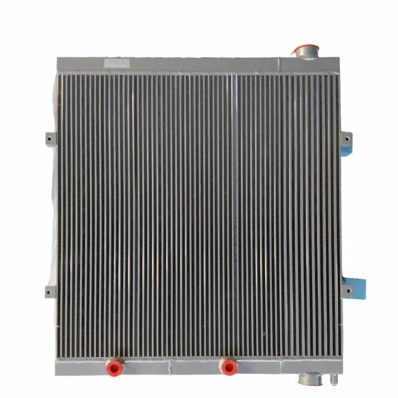
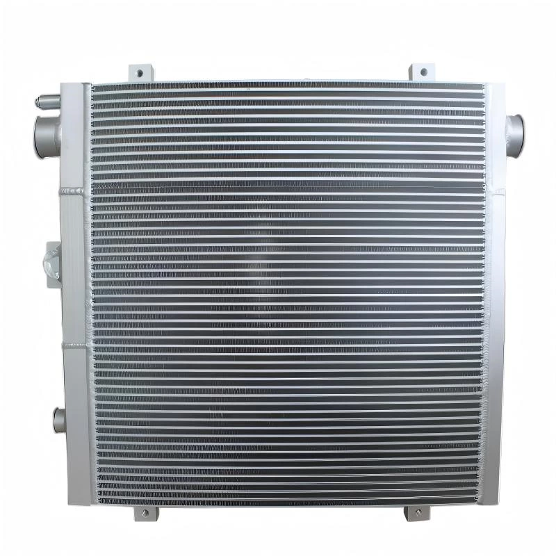
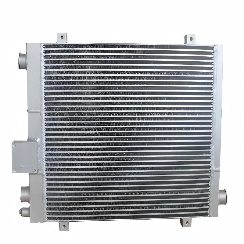
For custom aluminum hydraulic oil cooler or cooling-core projects, providing operating data together with drawings, connection details, installation space, and machine information makes it possible to evaluate both physical fitment and thermal requirements before production.