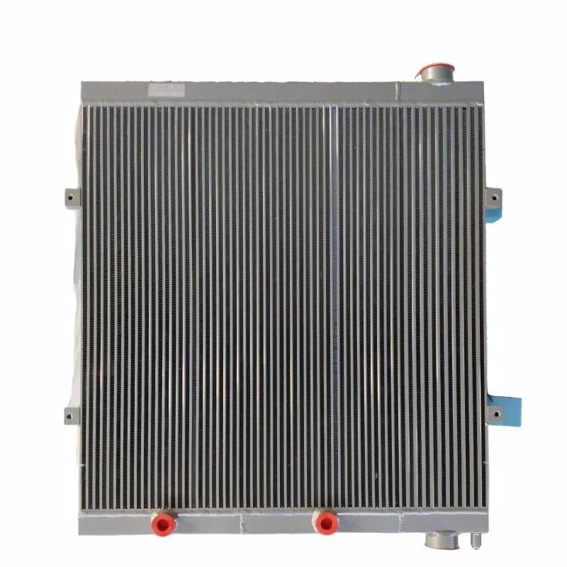
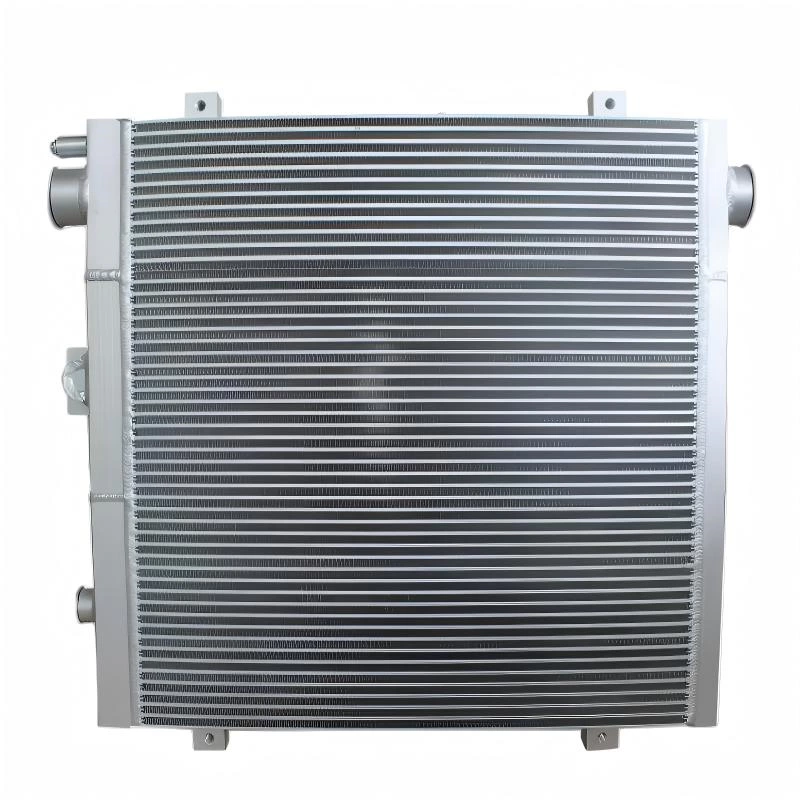
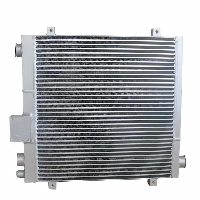
Key Design Factors for Plate-Fin Heat Exchangers in CNG Compressor Cooling
Cooling a CNG compressor is not simply a matter of finding a heat exchanger with enough surface area. Compression raises gas temperature, while each cooling stage must operate within limits for outlet temperature, pressure drop, working pressure, installation space, and long-term structural reliability.

A plate-fin heat exchanger can provide high heat-transfer area in a compact core, but its performance depends on how well the internal flow passages, fins, headers, connections, and brazed structure are matched to the actual compressor duty. A core that performs well at one flow rate or pressure condition may not behave the same way when compressor stage, gas temperature, operating cycle, or allowable pressure loss changes.
For CNG compressor cooling, thermal performance and structural reliability have to be designed together. A cooler that removes enough heat but creates excessive pressure loss—or cannot tolerate repeated pressure and temperature changes—is not a successful design.
For a general explanation of plate-fin heat exchanger construction and operating principles, see our introduction to plate-fin heat exchangers. The discussion below focuses specifically on the engineering conditions that matter when a plate-fin core is considered for CNG compressor cooling.
Why CNG Compressor Cooling Is a Different Design Problem
Gas temperature rises during compression because mechanical work is added to the gas. In a multi-stage compressor, this heating occurs repeatedly, so cooling may be required between stages as well as after the final compression stage.
That creates a more demanding design problem than simply cooling a steady liquid stream. The heat exchanger may see changing gas flow, different inlet temperatures between compressor stages, pressure variations, and repeated start-stop cycles. At the same time, pressure loss through the cooler must remain low enough that the compressor does not spend unnecessary energy overcoming resistance downstream.
The important point is that heat load, pressure level, pressure drop, and temperature cycling are linked. Optimizing only one of them can create problems elsewhere in the system.
| Design Condition | Why It Matters |
|---|---|
| Gas flow rate | Determines mass flow and strongly affects both heat transfer and pressure drop. |
| Gas inlet temperature | Defines the thermal load entering the cooler. |
| Target outlet temperature | Defines how much sensible heat must be removed. |
| Working pressure | Influences structural requirements for the core, headers, and connections. |
| Allowable pressure drop | Limits how much flow resistance the cooler can introduce. |
| Operating cycle | Determines how often the core experiences thermal and pressure changes. |
Start With the Actual Thermal Duty
Core size should not be the first design input. The first question is how much heat must be removed from the gas under the required operating condition.
For a simplified sensible-cooling calculation, the heat-removal requirement can be expressed as:
Q = ṁ × Cp × ΔT
Q = required heat-transfer rate
ṁ = gas mass flow rate
Cp = specific heat capacity of the gas
ΔT = required gas temperature reduction
The relationship is useful for establishing thermal duty, but real heat exchanger design requires more than inserting three values into a formula. Gas properties vary with composition, temperature, and pressure. Cooling-medium temperature also changes the available temperature difference, while the compressor may operate over more than one flow condition.
Design Around the Operating Envelope
A cooler sized only for a nominal compressor condition can become undersized when inlet temperature increases or cooling-medium temperature rises. Conversely, designing only for an extreme peak without understanding how long that peak lasts can produce an unnecessarily large or restrictive core.
The engineering input should therefore define the expected operating envelope: minimum and maximum gas flow, expected inlet temperature range, target outlet temperature, working pressure, and the temperature of the air or liquid used to carry the heat away.
Pressure Drop Is a Design Limit, Not a Secondary Detail
A compact heat exchanger can increase heat-transfer intensity by using narrow passages and extended surfaces, but the same geometry can also increase flow resistance. For compressor cooling, that trade-off matters because every unnecessary pressure loss becomes part of the system burden.
Pressure drop is created not only inside the heat exchanger core. Headers, distributors, transitions, fittings, and connection geometry all contribute to the total resistance between the compressor outlet and downstream equipment.

If Passages Are Too Restrictive
Gas velocity and frictional losses increase. The cooler may achieve strong local heat transfer, but compressor efficiency can be penalized by excessive pressure loss.
If Passages Are Too Open
Pressure drop may fall, but gas-side heat-transfer intensity can also decrease. More core volume or additional surface area may then be required to achieve the target outlet temperature.
The correct design is therefore not the core with the lowest pressure drop or the highest heat-transfer coefficient. It is the configuration that meets the required thermal duty while staying inside the allowable system pressure loss.
Working Pressure Changes the Structural Problem
Thermal calculations alone do not determine whether a plate-fin heat exchanger is suitable for a compressor application. The core must also withstand the specified internal pressure and the loads transferred through headers, connections, and mounting points.
Pressure acts repeatedly over the internal flow passages and brazed interfaces. In a compressor that cycles frequently, the structure may experience many pressure changes over its service life rather than one constant static load.
Static Pressure and Pressure Cycling Are Not the Same
A component can remain below its static strength limit and still accumulate fatigue damage when stress is repeated enough times. The number of cycles, pressure range, local geometry, and joint quality therefore matter in addition to maximum operating pressure.
This is why working pressure, maximum allowable pressure, expected cycling frequency, and test requirements should be defined before the core geometry and connection structure are finalized.
Pressure rating should not be treated as a label added after thermal design. It is one of the inputs that shapes the heat exchanger structure from the beginning.
Temperature Gradient Can Become a Structural Load
Temperature difference is necessary for heat transfer, but a large or uneven temperature gradient also causes different parts of the aluminum structure to expand by different amounts.
In a brazed plate-fin core, plates, fins, side bars, headers, and brazed interfaces form one integrated structure. If one region heats or cools faster than another, local expansion is restrained by the surrounding material. That restraint creates thermal stress.
This becomes more important when temperature changes are repeated. Compressor start-up, load changes, shutdown, and changing ambient or cooling-medium conditions can repeatedly move the structure through different temperature states.

Why Brazed Areas Deserve Attention
The brazed connection between fins and adjacent plates is not merely a thermal contact. It also contributes to structural continuity inside the core. Research on plate-fin heat exchangers has shown that temperature gradients can generate stresses that concentrate around brazed-joint regions, making local joint behavior an important part of structural analysis.
For CNG compressor cooling, the exact temperature range is different from cryogenic LNG service, so LNG stress values should not be transferred directly. The useful engineering principle is broader: thermal gradients and repeated temperature changes can create mechanical loads inside a brazed core.
Flow Distribution Determines How Much of the Core Is Really Working
A heat exchanger may have enough total surface area and still perform poorly if the gas is not distributed evenly across the available passages.
If too much flow enters one region of the core, that area experiences higher velocity and pressure loss. Other passages may carry less flow and contribute less useful heat transfer. The result can be lower effective core utilization together with larger local temperature differences.
Headers and Distributors Matter
The job of the inlet header is not simply to connect a pipe to the core. It must introduce the gas into the flow passages with an acceptable distribution pattern.
Header geometry, inlet position, distributor design, passage resistance, and core width all influence how evenly the gas is divided. Poor distribution becomes more difficult to correct as flow rate and core width increase.
A large core is not automatically an effective core. The useful heat-transfer area is the area that receives the intended flow.
Fin and Passage Geometry Must Balance Three Requirements
In a plate-fin heat exchanger, fins increase surface area and influence flow behaviour. For compressor cooling, their geometry should be selected as part of a wider balance between thermal performance, pressure drop, and structural support.
| Design Goal | What Usually Helps | Possible Trade-Off |
|---|---|---|
| Increase heat transfer | More effective surface area and stronger fluid-side mixing | Pressure drop may increase |
| Reduce flow resistance | More open passage geometry | Heat-transfer intensity may decrease |
| Improve structural support | Stable fin-to-plate contact and appropriate internal support | Geometry may become heavier or more restrictive |
For this reason, fin selection should not be based on surface area alone. The correct geometry depends on gas flow, allowable pressure drop, heat-transfer target, pressure requirement, and the mechanical role the fin structure must perform inside the brazed core.
Cooling-Medium Conditions Can Be as Important as Gas-Side Conditions
A gas-side thermal duty tells only half of the story. Heat can only leave the compressed gas if the secondary side can accept it.
Depending on the system, the cooling medium may be ambient air or another fluid circuit. Its inlet temperature, flow rate, and available temperature rise directly affect the heat exchanger's ability to reach the required gas outlet temperature.
Do Not Use Ambient Temperature as a Placeholder
For air-cooled equipment, the air entering the heat exchanger may be warmer than the outdoor ambient temperature if it passes through an enclosure or receives recirculated discharge air. For liquid-cooled arrangements, coolant temperature may rise as other components reject heat into the same circuit.
The design should therefore use the actual or worst-case inlet condition expected at the heat exchanger, not simply a convenient environmental value.
Installation Geometry Can Change the Final Design
Available space affects more than overall dimensions. It can determine core aspect ratio, header orientation, connection location, airflow path, service access, and how loads are transferred into the heat exchanger.
A long, shallow core may behave differently from a short, deep core even when both contain similar heat-transfer area. Connection orientation can also affect header design and flow distribution.
Space
Maximum height, width, and depth constrain the core geometry.
Connections
Port size and position influence pressure loss, header layout, and integration.
Support
Mounting should control movement without imposing unnecessary external stress on the core.
These constraints should be supplied early in the design process. Redesigning headers or connections after the thermal core has already been fixed often introduces avoidable compromises.
Brazed-Joint Quality Connects Manufacturing to Reliability
A plate-fin heat exchanger depends on many brazed interfaces working together as one pressure-containing and heat-transferring structure. Thermal calculations can specify an appropriate core, but manufacturing quality determines whether the physical product actually matches that design intent.
Joint consistency, component fit-up, surface condition, brazing preparation, furnace control, and dimensional stability all influence the finished assembly. Local defects can reduce the effective load-carrying area of a joint even when the overall core looks correct from the outside.
The manufacturing process therefore needs to support both heat-transfer performance and structural integrity. Leak testing and pressure testing verify different aspects of the finished product, while application-specific validation may also consider repeated pressure or thermal cycling.
The important distinction is that testing does not replace good design or controlled manufacturing. It verifies whether the finished exchanger satisfies the defined requirements.
What Data Is Needed Before Designing a CNG Compressor Heat Exchanger?
A useful engineering request should describe the actual operating condition rather than asking for a cooler based only on outside dimensions. The more complete the input data, the less the design has to rely on assumptions.
| Required Data | Why It Is Needed |
|---|---|
| Gas composition | Needed to establish thermophysical properties and material compatibility. |
| Gas mass or volumetric flow | Defines the flow condition and contributes directly to heat load. |
| Gas inlet temperature | Defines the hot-side starting condition. |
| Required gas outlet temperature | Determines the required temperature reduction. |
| Normal and maximum working pressure | Defines structural design conditions. |
| Allowable pressure drop | Limits acceptable gas-side flow resistance. |
| Cooling-medium type and inlet condition | Defines how much thermal driving force is available. |
| Compressor stage | Helps identify the expected pressure and temperature range. |
| Operating cycle | Provides context for repeated temperature and pressure changes. |
| Installation envelope | Constrains core size, orientation, headers, and connections. |
| Connection size and position | Affects integration, velocity, distribution, and pressure loss. |
For an existing installation, drawings, photographs, connection dimensions, and the original exchanger specification can also help establish the mechanical envelope. However, reproducing outside dimensions alone does not verify that a new core is thermally or structurally suitable for a different compressor duty.
Common Design Mistakes in CNG Compressor Cooling
Selecting the Core by Size Alone
Two heat exchangers with similar outside dimensions can have very different internal flow area, pressure drop, heat-transfer capacity, and pressure capability.
Ignoring Allowable Pressure Drop
A cooler can meet the outlet-temperature target and still be unsuitable if its gas-side restriction creates excessive system pressure loss.
Using Only One Rated Flow Condition
Compressors may operate across a wider envelope than the nominal design point. The exchanger should be checked at the conditions that actually control thermal and hydraulic performance.
Assuming Uniform Flow Through the Core
Thermal calculations that assume perfect flow distribution can overestimate useful core area when header or distributor geometry creates maldistribution.
Ignoring Pressure and Temperature Cycling
Maximum static pressure and steady-state temperature do not describe the repeated mechanical loading created by compressor start-stop operation and changing duty.
Treating Brazed Joints Like Base Aluminum
Brazed interfaces have their own geometry and local material conditions. Structural evaluation should consider the joint region rather than assuming every part of the assembled core behaves like homogeneous base material.
Leaving Installation Constraints Until the End
Late changes to ports, headers, mounting, or core orientation can disturb pressure drop, flow distribution, and mechanical loading. Packaging data should be treated as an early design input.
FAQ
What data is most important when sizing a CNG compressor heat exchanger?
Gas flow, inlet temperature, required outlet temperature, working pressure, allowable pressure drop, and cooling-medium conditions are the primary thermal and hydraulic inputs. Compressor stage, operating cycle, installation space, and connection layout are also needed for a practical design.
Why is pressure drop important in CNG compressor cooling?
Pressure drop represents resistance to gas flow through the exchanger and its connections. Excessive resistance can increase system losses even if the exchanger achieves the required outlet temperature, so thermal performance and allowable pressure loss must be evaluated together.
Can a larger plate-fin core always provide better cooling?
No. A larger external size does not automatically provide better effective heat transfer. Internal passage geometry, flow distribution, pressure drop, cooling-medium condition, and actual utilization of the core determine the final performance.
Why do temperature gradients matter in a brazed plate-fin heat exchanger?
Different temperatures cause different parts of the aluminum structure to expand by different amounts. Because the plates, fins, side structures, and brazed joints are connected, uneven expansion can generate local thermal stress, especially during repeated temperature changes.
Can the same heat exchanger be used for different CNG compressor stages?
Not automatically. Different stages can operate at different gas temperatures, pressures, flow conditions, and cooling duties. Suitability should be verified against the actual operating data and allowable pressure drop for each stage.
Conclusion
A plate-fin heat exchanger for CNG compressor cooling should be treated as both a thermal component and a pressure-containing structure. The design has to remove the required heat without introducing excessive pressure loss, while also handling working pressure, flow distribution, temperature gradients, repeated operating cycles, and installation constraints.
The most reliable design process starts with real compressor data rather than a target core size. Gas flow, temperatures, pressure, allowable pressure drop, cooling-medium conditions, operating cycle, and installation geometry should be defined first. Core geometry, headers, fins, connections, and structural requirements can then be developed around those conditions.
For custom aluminum plate-fin heat exchanger projects, complete operating data, drawings, connection details, and installation constraints provide a much stronger basis for engineering evaluation than dimensions alone.