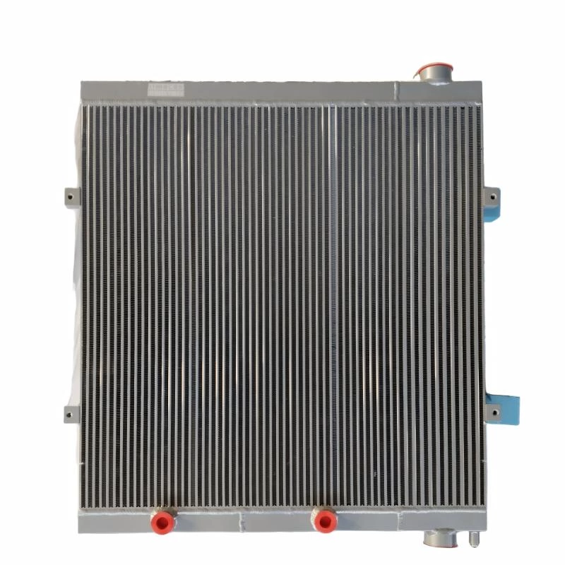
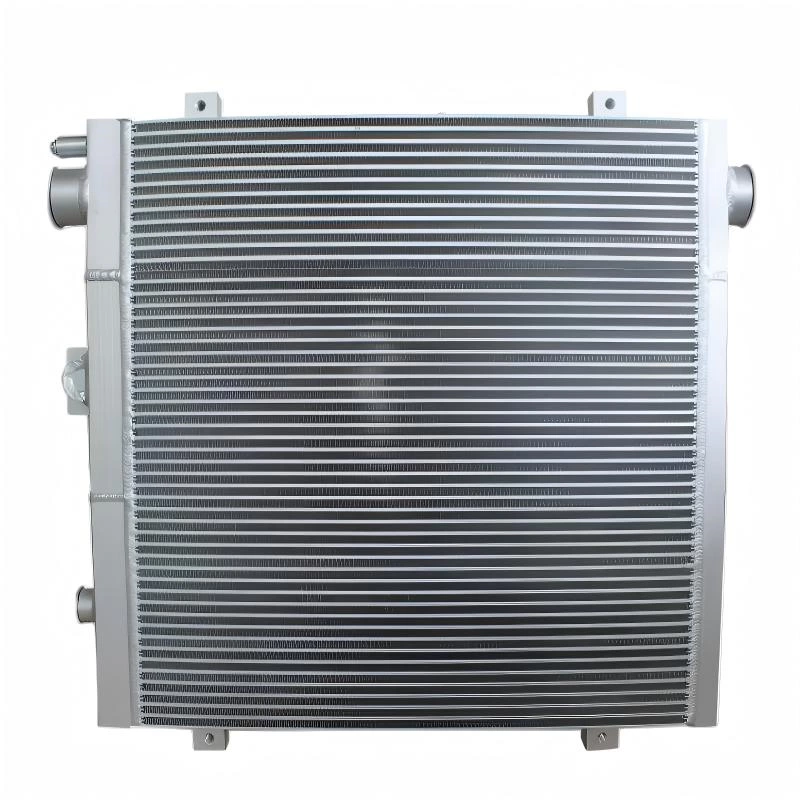
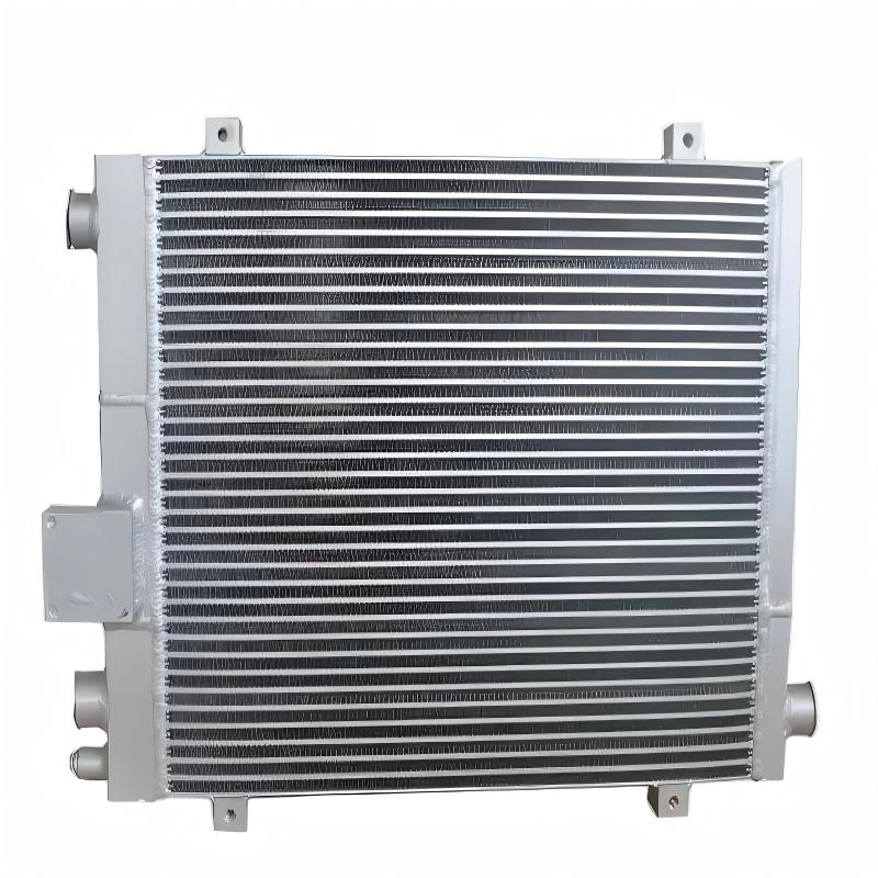
Radiator Heat Exchanger Design: Core, Fins, Tubes and Airflow
Radiator heat exchanger design is not determined by core size alone. Cooling performance depends on how the core, tubes, fins, fluid flow, and airflow work together under the actual operating conditions of the equipment.
A larger or thicker radiator may provide more heat transfer area, but it can also increase airflow resistance. Higher fin density can improve surface area, yet it may become less suitable in dusty environments. Tube arrangement can support efficient heat transfer, but poor flow distribution or excessive pressure drop can reduce overall system performance.
For industrial cooling applications, radiator design therefore needs to balance thermal performance, airflow, pressure, installation space, and working environment. This article explains how the main design elements affect cooling performance and what should be considered when developing or selecting a radiator heat exchanger.
Why Radiator Heat Exchanger Design Matters
A radiator heat exchanger removes heat from coolant, hydraulic oil, or another working fluid and transfers that heat to the surrounding air. The effectiveness of this process depends on both the fluid side and the air side of the heat exchanger.

Inside the radiator, the working fluid passes through tubes or internal flow channels. Heat moves through the tube walls into the fins, where airflow carries it away. If any part of this process is restricted, the cooling system may not achieve the required heat rejection performance.
| Design Factor | Main Effect |
|---|---|
| Core Size | Determines available heat transfer area and installation requirements |
| Core Thickness | Affects heat transfer area, airflow resistance, and packaging space |
| Tube Design | Influences fluid distribution, flow resistance, and heat transfer |
| Fin Structure | Controls air-side surface area and airflow resistance |
| Airflow | Determines how effectively heat is removed from the fin surface |
| Working Environment | Influences fin spacing, structural requirements, and contamination resistance |
For this reason, changing one radiator parameter often affects several others. Increasing core thickness, for example, may provide additional heat transfer area while also making it harder for the fan to move sufficient air through the entire core.
How the Radiator Core Affects Cooling Performance
The radiator core is the main heat exchange section of the system. Its height, width, and thickness influence available heat transfer area, airflow resistance, and how easily the radiator can be integrated into the equipment.
Core size needs to balance cooling demand with installation space. A larger core can provide more heat exchange area, but increasing dimensions without considering airflow or packaging can reduce overall system efficiency.

| Core Dimension | Design Impact |
|---|---|
| Height & Width | Determine much of the frontal heat exchange area and influence how much air can pass through the radiator. |
| Thickness | Adds tube rows and fin surface, but also increases the airflow path and air-side resistance. |
In industrial equipment, core height and width are often limited by fan position, shrouds, frames, hoses, nearby components, and the machine enclosure. This means the largest possible frontal area is not always practical.
Core thickness requires the same balance. A thicker radiator can increase heat transfer potential, but if the available fan cannot move enough air through the full depth of the core, airflow in the rear section may decrease.
The final radiator core dimensions should therefore be selected according to the required heat rejection, fan performance, airflow conditions, installation clearance, and the layout of the complete cooling system.
How Tube Design Influences Fluid Flow and Heat Transfer
Tubes form the main internal flow path of a radiator heat exchanger. Their size, arrangement, number, and connection layout affect how the working fluid moves through the core and how evenly heat is distributed across the heat exchange surface.
A well-designed tube layout should provide enough internal flow area to carry the required coolant or oil volume while maintaining effective contact with the surrounding fin structure. If the flow path is too restrictive, pressure drop can increase. If the distribution is uneven, some areas of the core may receive less fluid and contribute less to heat transfer.
Tube design needs to balance three things at the same time: fluid distribution, heat transfer area, and acceptable pressure drop.

Tube Size and Arrangement
Tube width, height, spacing, and quantity influence both fluid-side performance and the amount of surface available for heat transfer. Narrower or more densely arranged tubes can increase contact area, while larger flow passages may reduce restriction depending on the application.
The most suitable arrangement depends on the cooling medium, required flow rate, operating pressure, and available core dimensions. Hydraulic oil cooling, engine coolant systems, and other industrial applications may therefore use different internal layouts even when the external radiator size is similar.
Flow Path and Pressure Drop
The fluid must move through the radiator with enough residence time to release heat, but the path should not create unnecessary resistance. Excessive pressure drop can reduce system efficiency or place additional demand on pumps and other components.
Flow direction and pass arrangement also matter. Depending on the design, the working fluid may travel through a single-pass or multi-pass path before leaving the heat exchanger. The selected layout should support even distribution and stable cooling across the full core.
| Tube Design Consideration | Possible Effect |
|---|---|
| Tube Size | Affects internal flow area and fluid velocity |
| Tube Quantity | Influences total flow capacity and heat transfer area |
| Tube Spacing | Affects fin layout, airflow path, and core compactness |
| Flow Passes | Changes fluid travel distance and pressure drop |
| Header Distribution | Helps determine how evenly fluid enters different tubes |
For custom radiator projects, tube configuration should be reviewed together with flow rate, inlet and outlet temperature, pressure limits, and cooling medium. Changing the internal tube layout without considering these factors can affect both thermal performance and system resistance.
How Fin Design Affects Air-Side Performance
Fins largely determine how effectively heat moves from the radiator core into the surrounding air. By increasing the external surface area connected to the tubes, they allow more heat to be transferred into the airflow passing through the core.

| Fin Design Factor | Effect on Cooling |
|---|---|
| Fin Density | Higher density increases heat transfer surface area but reduces the open space available for airflow. |
| Fin Spacing | Wider spacing can help maintain airflow in dusty, dirty, or debris-heavy operating environments. |
| Fin Height | Influences available air-side surface area and the resistance encountered by airflow. |
| Fin Geometry | Affects how air moves through the core and how effectively it contacts the metal surface. |
More fins do not automatically mean better cooling. A dense fin structure can perform well in clean conditions, but it may restrict airflow more quickly when dust or debris accumulates. Fin design therefore needs to match the fan capability, core thickness, cooling requirement, and actual operating environment.
For construction machinery, mining equipment, agricultural machines, and other heavy-duty applications, maintaining stable airflow during continuous operation can be more important than simply maximizing fin density.
Why Airflow Is Critical in Radiator Heat Exchanger Design
A radiator heat exchanger can only remove heat effectively when sufficient air passes through the fin surface. For this reason, airflow should be considered as part of the radiator design rather than treated as a separate system parameter.
Cooling requires both fluid-side and air-side performance: the working fluid transfers heat into the core, while airflow removes that heat from the fins.
Fan capacity determines how much air can be moved through the radiator, while the shroud and surrounding air path determine how much of that airflow actually passes through the core. Fan size, speed, blade design, and distance from the radiator can all affect airflow distribution.
A thicker core or denser fin structure generally creates a more restrictive air path. If fan capability is insufficient, airflow through the deeper sections of the core may decrease and the additional heat transfer area may provide limited benefit.
| Airflow Factor | Design Impact |
|---|---|
| Fan Capacity | Determines the available airflow and pressure needed to move air through the radiator core. |
| Fan-to-Core Distance | Affects how evenly airflow is distributed across the heat exchange surface. |
| Shroud Design | Helps direct airflow through the core and reduce bypass around the radiator. |
| Core Thickness | Changes the distance and resistance that air must overcome through the core. |
| Fin Density | Balances available heat transfer area against air-side resistance. |
| Equipment Layout | Panels, screens, hoses, filters, and nearby components can restrict inlet or outlet airflow. |
The complete air path should be evaluated from the point where cooling air enters the equipment to where heated air exits. Large gaps around the shroud, blocked inlet areas, or nearby components can allow air to bypass the core or increase system resistance.
Airflow in Dusty and Debris-Heavy Environments
Outdoor equipment introduces another design consideration. Dust, fibers, leaves, and other debris can gradually collect between the fins, reducing the open airflow area and increasing resistance through the radiator.
A fin arrangement that performs well in clean conditions may therefore lose effectiveness more quickly in construction, mining, or agricultural applications. Wider fin spacing, suitable core depth, adequate fan capability, and accessible cleaning space can help maintain more stable airflow during operation.
The best radiator design for a harsh environment is not necessarily the one with the highest fin density. The design should maintain a practical balance between heat transfer surface, airflow, contamination resistance, and long-term cooling performance.
How Core, Tubes, Fins and Airflow Work Together
Radiator heat exchanger performance is the result of several design elements working as one system. Core size determines the available heat exchange area, tubes carry the working fluid, fins transfer heat to the air, and the fan supplies the airflow needed to remove that heat.

If one of these elements is poorly matched, increasing another parameter may not solve the problem. For example, adding more fins can increase surface area, but it may also restrict airflow. Increasing the number of tubes can improve fluid-side contact, but it may also change flow distribution and pressure drop.
Effective radiator design is a balance: thermal area, fluid flow, airflow resistance, pressure drop, installation space, and operating environment must all be considered together.
For this reason, radiator heat exchanger design should be based on the complete application rather than on a single target such as maximum core thickness or maximum fin density.
Design Considerations for Different Industrial Applications
The same radiator heat exchanger design is not suitable for every machine. Industrial applications can differ significantly in heat load, operating time, vibration, contamination level, available airflow, and installation space. These differences should influence the final core, tube, fin, and airflow configuration.
| Application | Main Design Considerations |
|---|---|
| Construction Machinery | Dust resistance, vibration, continuous load, fin spacing, and strong structural design |
| Heavy-Duty Trucks | Compact installation, stable airflow, road vibration, and long operating cycles |
| Industrial Equipment | Continuous thermal load, fixed installation space, fan performance, and system integration |
| Agricultural Machinery | Dust, fibers, crop debris, cleaning access, and changing outdoor conditions |
| Hydraulic Systems | Oil flow, operating pressure, fluid temperature, pressure drop, and compact core design |
Construction and agricultural equipment usually require more attention to contamination and airflow retention, while stationary industrial systems may place greater emphasis on continuous thermal performance and integration with an enclosure or fan system.
For mobile equipment, vibration and packaging constraints can also influence core thickness, mounting layout, connection positions, and overall structural design.
Common Radiator Heat Exchanger Design Mistakes
Many radiator performance problems come from poor system matching rather than insufficient heat transfer area. Core thickness, fin density, tube layout, fan capacity, and installation space all influence each other, so changing one parameter without checking the rest of the system can easily create new problems.
| Design Mistake | What Can Go Wrong |
|---|---|
| Increasing core thickness without checking airflow | A thicker core adds heat transfer area, but it also increases air-side resistance. If fan capacity is limited, airflow through the rear section of the core may decrease. |
| Using overly dense fins in dusty environments | Dense fins can provide more surface area, but dust and debris may block the air passages more quickly and reduce cooling performance during operation. |
| Ignoring fluid-side pressure drop | Tube arrangement and flow paths that create excessive restriction can increase pressure drop and reduce the efficiency of the cooling circuit. |
| Designing the radiator separately from the fan and shroud | Poor airflow distribution or excessive bypass can limit cooling even when the radiator core itself is correctly sized. |
| Focusing only on external dimensions | Radiators with the same height, width, and thickness may perform differently because of tube layout, fin geometry, flow arrangement, and airflow conditions. |
A larger or denser radiator is therefore not automatically a better design. The core needs to match the actual heat load, available airflow, fluid flow, pressure limits, installation space, and operating environment.
For industrial equipment, the most effective approach is to evaluate the radiator together with the fan, shroud, piping, mounting space, and working conditions before the final core specification is confirmed.
What Information Is Needed for a Custom Radiator Heat Exchanger Design?
Custom radiator development should begin with the actual operating conditions of the equipment. The more complete the application data is, the easier it is to evaluate the required core structure and avoid unnecessary design changes later in the project.
You can provide a technical drawing, existing sample, OE information, or confirmed dimensions. For a new application, thermal and operating data can be used together with the available installation space to develop the radiator specification.
- Cooling medium
- Required flow rate
- Inlet and outlet temperature
- Ambient air temperature
- Available airflow or fan information
- Operating pressure
- Allowable pressure drop
- Available core height, width, and thickness
- Connection and mounting requirements
- Working environment and duty cycle
- Technical drawings, OE information, or existing samples
Based on these requirements, core dimensions, tube layout, fin structure, flow direction, headers, and connections can be evaluated together rather than selected independently.
For projects where standard specifications do not meet the required cooling or installation conditions, a custom radiator core can be developed around the actual thermal and mechanical requirements of the equipment.
For custom industrial cooling projects, an experienced radiator and heat exchanger manufacturer can support the process from design review and core development to brazing, testing, and production.
Frequently Asked Questions About Radiator Heat Exchanger Design
What are the main factors in radiator heat exchanger design?
The main factors include core size, tube arrangement, fin structure, fluid flow, airflow, pressure drop, operating temperature, installation space, and working environment. These parameters should be evaluated together because changing one factor can affect several others.
Does a thicker radiator core provide better cooling?
Not always. A thicker core can increase heat transfer area, but it also increases the distance air must travel through the fins. If the fan cannot provide enough airflow, the added thickness may offer limited improvement and can even increase air-side resistance.
How does fin density affect radiator performance?
Higher fin density increases heat transfer surface area, but it also reduces the open space available for airflow. In dusty or debris-heavy environments, a lower or more open fin density may provide more stable long-term airflow.
Why is tube arrangement important?
Tube arrangement influences fluid distribution, heat transfer area, flow velocity, and pressure drop. A suitable layout helps distribute coolant or oil evenly across the core while maintaining acceptable system resistance.
How important is airflow in radiator heat exchanger design?
Airflow is critical because it removes heat from the fin surface. Fan performance, shroud design, core thickness, fin density, inlet restriction, and outlet clearance all affect how much air can pass through the radiator.
Can the same radiator core design be used for different applications?
Not always. Construction machinery, trucks, agricultural equipment, hydraulic systems, and stationary industrial equipment can operate under very different heat loads, contamination levels, pressure conditions, and airflow environments. The radiator core design should therefore match the specific application.
What information is required for a custom radiator heat exchanger?
Useful information includes the cooling medium, flow rate, inlet and outlet temperatures, ambient temperature, available airflow, working pressure, allowable pressure drop, installation dimensions, mounting details, drawings, OE information, or an existing sample.
Can a radiator heat exchanger be developed from an existing sample?
Yes. An existing radiator or core can be used as a reference for dimensions, tube layout, fin structure, headers, connections, and mounting details. Sample-based development is especially useful for discontinued, modified, or non-standard equipment.
Conclusion
Effective radiator heat exchanger design depends on more than selecting a large core or increasing fin density. Core dimensions, tube layout, fin structure, fluid flow, airflow, pressure drop, and the operating environment all need to work together as part of the complete cooling system.
For industrial applications, the best design is usually the one that balances cooling performance with airflow resistance, fluid-side pressure drop, installation space, structural reliability, and real operating conditions.
When standard specifications cannot meet the required thermal or installation conditions, a custom radiator core can be developed from application data, drawings, dimensions, OE information, or an existing sample.